Contents
Concept of Quads and Drivelines
Drivelines are used to indicate to the AI where to drive and to determine the order of karts: if a kart is on the driveline, it is known how much of the track it has driven, and allows to compare the progress of karts. If a kart is off the driveline, the closest driveline point is picked to determine how far that kart has driven when comparing the distances of karts, and to determine where to drive to.
All places that a kart is allowed to drive on are marked by quads. Quads need not to be connected (though usually are). A sequence of quads together make a driveline, indicating in which order the AI should drive on the quads. Example:
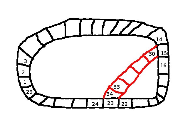
A driveline section is a sequences of quads connected to each other. These driveline sections are then connected to create the full drivelines for a track. In the example above there would be two driveline sections: the black main driveline creating the lap, and the driveline in red indicating a shortcut (or alternative path) for the karts.
In blender the quads of a driveline section are created from a simple mesh:
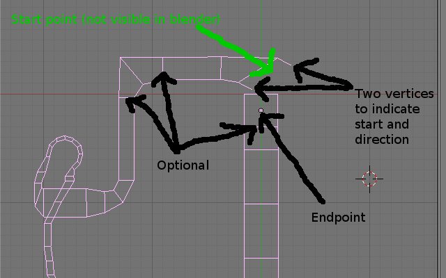
The beginning of a driveline section is marked by two unconnected edges. The start point of a driveline is the middle point of the two end vertices of the edges. The end point is the middle point of the four vertices of the last quad. The edges connecting corresponding vertices from the left and right side are optional. So if you want to divide a quad into two (e.g. to better model the shape of the track, or to help the AI) you can just add the two vertices, you do not have to connect them. It is important though that both sides of the drivelines contain the same number of vertices (otherwise the quads can’t be created properly). If you convert the main track as described in the track making tutorial the created mesh will automatically have the same number of points on each side.
There are two reasons why you might want to split a single driveline section into smaller driveline sections:
- A driveline section can be marked as ‘insivisible’, i.e. it will not be displayed in the minimap. This should be used for hidden shortcuts that need to be discovered by the player. This is done by giving the driveline the property ‘invisible’ with a non-zearo value.
- (not yet implemented): driveline section can be marked as ‘disabled’, meaning it will not be used (nor displayed) in the game. This can be used to force the AI to take a certain way and therefore make sure that the AI can drive on all possible paths.
The track export script distinguish between two kind of driveline sections:
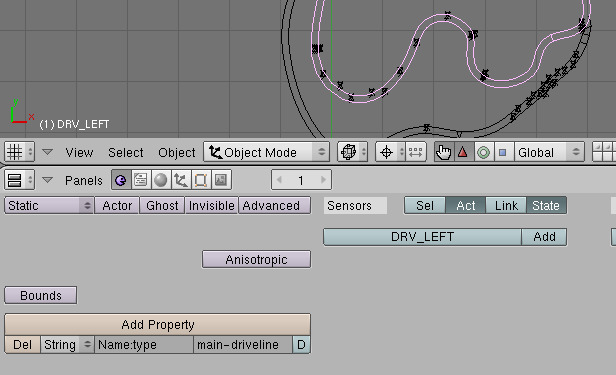
Main driveline sections
The main driveline which indicates the ‘main’ way in which karts should drive. The quads of the main driveline must form a single lap. A driveline section is marked to be part of the main driveline by giving it the type “main-driveline”.
The example above shows a single driveline section only. The order in which the main driveline sections are connected is determined as follows:
- The main driveline section with a start point closest to (0,0,0) is selected first.
- From all remaining main driveline sections the one with the start point closest to the end point of the last selected main driveline section is selected next.
The last step is then repeated till all main driveline sections are selected, and therefore the order in which the main driveline sections are connected is determined. The quads are then created from the separate driveline sections, and one quad is added from the last added driveline section to back to the first driveline section. This creates the main lap.
Note: Depending on experience we might either add quads to connect each driveline section, or not add the one driveline section between the last and the first section.
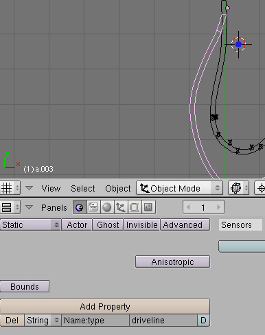
Normal driveline sections
Normal driveline sections are indicated by giving the mesh the type property “driveline”. These drivelines are used to create ‘alternative’ ways for the track to drive on.
The procedure with which these driveline sections are added is similar to the procedure above:
- Select all main driveline sections.
- From all normal driveline sections the one with a starting point closest the center point of any quad in the selected drivelines is selected. A new connection is made from the closest quad to the newly selected driveline section.
This procedure is then repeated till all quads have been added. Note that by moving the two start vertices you can exactly control which quad is selected as the predecessor of a normal driveline section: just move the two vertices close to the center of the quad you want it to be connected from.
FIXME: What about the end of a newly selected quad? This is added as well???
Detailed concept: QuadGraph
While the description so far is exactly what is supported by the track exporter, the actual concept implemented in STK allows more complicated structure. This is done by maintaining two data structures: one containing the list of all quads, and one describing how the quads are connected with each other, the so called quad graph. The main difference between the two data structures is that one quad in the list of all quads can be used several times in the graph. The graph consists of nodes - as a default, each quad corresponds to a graph node with the same number - this is exactly what the track exporter assumes. But this is not necessary: A part of the track might not be used for a particular race (think of a city track where several different race tracks can be defined.
The graph defines for each graph node which quad it belongs to, and which are the possible successors. Usually each quad will have exactly one successor, but in case of a shortcut or branch of the track it might have more than one.
Given the quad definitions from the picture, the following graphs could be defined:
Simple Loop
A graph with nodes 1 to 29, corresponding to the quads 1 to 29. The order is then
1 → 2 → 3 → ... → 29 → 1.

This defines a simple loop, driven in clockwise direction. The shortcut is not allowed (for the AI, there is no restriction where the players are allowed to drive).
Reverse Loop
A graph with nodes 1 to 29, corresponding to the quads 1 to 29 and the graph:
1 → 29 → 28 → ... → 2 → 1.
This gives a similar simple loop as the one above, but it is driven in reverse (ie. counter-clockwise).
Simple Loop with Shortcut
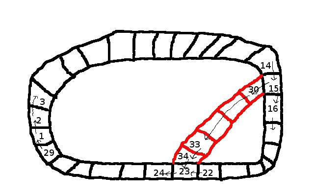
For this we need a graph with 34 nodes, corresponding to the 34 quads. The main loop will be defined as in example 1, but additionally we add:
15 → 30 → 31 ... → 34 → 23
This allows the AI to pick any of the two ways (the criteria for which way is picked are not defined yet - atm it’s a random selection).
The numbers indicate the number of the quads. This part does not define in which order the quads should be driven, or if the shortcut is to be used or not, it only defines which part of the track can be used.
A Loop Inside of the Track
The driveline structures also allows us to define a loop, i.e. forcing the AI to drive a circle before continuing, see picture:

(note that this is most likely an absurd example only - for a track like this to be fair the player karts would have to do the same loop, which means there must be a mean to indicate this to the player, which we currently don’t have).
To do this, we need additional graph nodes for the sections that are driven twice. So graph nodes 1 to 34 corresponds to the quads 1 to 34, and then additional graph nodes 35 to 43 which are mapped to the quads 15 to 23 (again). So the quads 15 to 23 have each two graph nodes associated with them, but each graph node still has exactly one quad. Then we can define the following graph:
1 → 2 → ... 14 → 15 → 16 → ... → 23 → 34 → 33 → ... → 30 → ...
This defines the first part of the loop: driving backwards on the shortcut to graph node 30 (which is quad 30). Then we use quad 15 for the second time, so we use the additional graph nodes here:
... 30 → 35 [15] → 36 [16] → ... → 43 [23] → 24 → 25 → ... → 29 → 1
In [] are the corresponding quad numbers for the graph nodes 35 to 43. By having the additional graph node layers the AI will simply follow the graph till the end (so there are no loops in the graph, except for starting a new lap), but the mappings of graph nodes to quads force the AI to drive a loop.